Visual Cues
This feature allows you to display visual cues as custom icons on both Trees and Grids to highlight components depending on any record field.
You need to abilitate visual cues by checking the option User Interface → ![]() Enable Visual Cues
Enable Visual Cues
Example
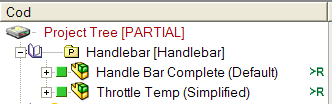
Suppose you want to mark some preferred or special components in the User Interface:
Visual Cues settings are stored in the definition file SCHEMA\IMG\DBWVisualCuesDef.txt
To set Visual Cues preferences you can use the Visual Cues Manager in the MechworksPDM ShortCut Bar.
See details about definition file (expert users only)
;--------------------------------------------------------------
; DBWVisualCuesDef.txt
;
; DBWorks Visual Cues Definition File
;
;--------------------------------------------------------------
; "<field name>","<field value pattern>","<Image Definition>",<Img width>,<Position Code>,<Tree Img Offset>,<Grid Img Offset>
;
; <Image definition>::=
; a .BMP/.JPG/.TIF/.PCX/.TGA file name, or .
; @Line,<pen width>,R,G,B
; @Cross,<pen width>,R,G,B
; @Rectangle,<pen width>,R,G,B
; @Ellipse,<pen width>,R,G,B
;
; <Position Code> 0: full row; 1:icon; 2: text; 3: right-side full row;
;
"PREFERENCE_INFOS", "Preferred*", "PreferredItem.BMP", 20, 1, -25, -10
"PREFERENCE_INFOS", "Not-Preferred*", "@Cross,3,255,0,0", 0, 2, 0, 0
"PREFERENCE_INFOS", "Special*", "SpecialItem.JPG", 30, 0, 10, -10
"T", "A", "dbwscbar149.bmp", 18, 3, -24, -24
Let see in details:
field name |
This field must be enclosed within the QUOTATION characters "." ( ANSI chr 34 ). The name of a database field; the field must appear only in the main database views ( ASSEMBLY,PART,DRAWING,GENERIC) that may have visual-cues displayed in the MechworksPDM User Interface |
|---|---|
field value pattern |
This field must be enclosed within the QUOTATION characters "." ( ANSI chr 34 ). A pattern against which the comparison of the field value will be performed, to know if the document must have a visual-cue displayed or not; it can contain all the valid regular expression characters like *,?,[..], etc.; in the example above, "Preferred*" means that if the field value begins with "Preferred", the document will be displayed with a visual-cue |
image definition |
This field must be enclosed within the QUOTATION characters "." ( ANSI chr 34 ). It may be of two types: 1.a .BMP/.JPG/.TIF/.PCX/.TGA file that must be located in the shared SCHEMA\IMG folder; consider that the visual-cues are displayed in the Trees and Grids rows, so the height and width of this image should not exceed the 100-200 pixels ( the image will however be stretched in the proper display area, but more large are the source image files, more time is needed for the stretching ) 2.a SHAPE definition with the following format: •Shape: Line | Rectangle | Cross | Ellipse •PenWidth: a number between 0 and 10; the pen's width in pixels with which the shape will be drawn •R,G,B: The RGB representation of the color for the shape ( each component in the range 0 - 255 ; ex: Red=255,0,0 Green=0,255,0 Blue=0,0,255 Exampleto draw a red cross with a pen of width = 3 pixels: @Cross,3,255,0,0 |
Image Width |
The width, in screen units, of the image; |
Position code |
This field is meaningful only when displaying the Visual Cues in the Trees:
The <Tree Img Offset> and <Grid Img Offset> parameters must be negative. 4: the visual cue image will be placed on icon for the Tree and left side for the Grids
|
Tree Img Offset |
This field is meaningful only when displaying the Visual Cues in the Trees: it indicates the offset ( positive or negative ) to be added to the left position of the Tree's Document rectangle for displaying the Visual Cue image |
Grid Img Offset |
This field is meaningful only when displaying the Visual Cues in the Grids: it indicates the offset ( positive or negative ) to be subtracted from the right position of the Grid's ID cell minus the image width, for displaying the Visual Cue image |
Performance considerations
The Visual Cues engine query the database for each distinct field name listed in the Visual Cues definition file; for this reason it is suggested to avoid to have many distinct field names, trying to group them in one or two fields on which to execute the database queries.
Visual Cues Development
To facilitate the development and setup of the Visual Cues, the command DBWShell("ReloadLookUpTables") reloads also the Visual Cues definition file, so permitting to show the updated values on the fly.
Example
Consider one of the rows in the example above:
"PREFERENCE_INFOS","Preferred*","PreferredItem.bmp", 20,1,-25,-10
Let see details (from left to right):
"PREFERENCE_INFOS" |
It is the name of the database field to be queried for it's value; it can be an existing field, or it can be created for the purpose of displaying visual cues |
|---|---|
"Preferred*" |
It is the pattern against to the value of the field will be matched; the star "*" means that every value following Preferred is accepted, so values like "Preferred Item","Preferred Component","Preferred Part" all will match the assigned patter |
"PreferredItem.BMP" |
It is the image file to be displayed; it will be searched in the shared SCHEMA\IMG folder. |
20 |
It is the assigned image width on which the source image will be stretched. The height is automatically assigned by MechworksPDM and it is always equal to the Tree's or Grid's ROW height. |
1 |
It is the position code, and indicates that you like to display the image near the ICON of the Document, for the Trees; for the Grids it is always displayed on the right side of the ID cell. |
-25 |
It is the offset that will be added to the left position of the image. Since it is negative, it will move the image on the LEFT. A positive value will move the image to the RIGHT. |
10 |
For the Grids, it is the offset to be added to the right most position of the ID cell, subtracted of the image width. Since it is negative, it will move the image on the LEFT. A positive value will move the image to the RIGHT. |
Support for tables different from DOCUMENT or other database VIEWS
You can define criteria for setting visual cues that depend on data stored in other tables of the main database.
Read more about the tool to manage here.
Example
"@SQL1","(EXTRA_CAD_DATA::SUPPLIER_ID::ID)SUPPLIER_NAME LIKE 'aa%'","dbwscbar140.bmp",20,1,-55,0
The same is possible with VIEWS of the database, with the following syntax:
"<nameOfQuery>","(<YOURVIEW>::<LINKFIELD1>::<LINKFIELD2>)<YOURVIEWFIELD> <condition> ...
Example
"@SQL2","(PART::UNIQUE_ID::UNIQUE_ID)T='P'","@Line,2,255,0,0",0,1,0,0
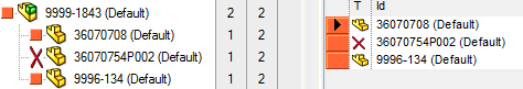
Visual cues and attachments
A useful way to use the visual cues can be the mark, in the tree, of documents that has file attachments.
![]()
the file definition for such usage is like following:
"@SQL1","(DBW_ATTACHMENTS)1=1","DBW_Attachment.ico",16,3,-25,-25
of course the icon must exist as st exist as SCHEMA\IMG\DBW_Attachment.ico
Visual cues and SQL conditions
To express specific criteria for showing visual cues, you may need an SQL condition.
Example
In the following example see how to show a different icon in the same separate column (see Dynamic Tree Columns for details) for different cost values:
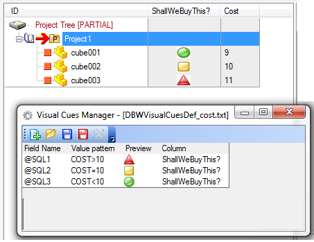
the definition file is as follows:
"@SQL1","COST>10","dbwscbar39.bmp",20,0,0,0,"ShallWeBuyThis?"
"@SQL2","COST=10","dbwscbar40.bmp",20,0,0,0,"ShallWeBuyThis?"
"@SQL3","COST<10","dbwscbar41.bmp",20,0,0,0,"ShallWeBuyThis?"
Disable default visual cues
For improving the performances in environments where, for example, the Task Manager is still not in production, the keyword @NO_AUTOMATIC_VISUAL_CUES can be added to the DBWVisualCuesDef.txt definition file.
When declared, the following automatic visual cues are not added automatically:
"@SQL9999","(DBW_ATTACHMENTS)1=1","DBW_Attachment.ico",16,3,-8,-16
"@SQL9998","(DBW_TASK_COMMANDS)A.TASK_STATE=3","taskMan_DONE.ico",16,3,-16,-32
"@SQL9997","(DBW_TASK_COMMANDS)A.TASK_STATE=6","taskMan_ERROR.ico",16,3,-16,-32
"@SQL9996","(DBW_TASK_COMMANDS)A.TASK_STATE=2","taskMan_EXEC.ico",16,3,-16,-32
"@SQL9995","(DBW_TASK_COMMANDS)A.TASK_STATE=4 ","taskMan_PAUSE.ico",16,3,-16,-32
"@SQL9994","(DBW_TASK_COMMANDS)A.TASK_STATE=0","taskMan_QUEUE.ico",16,3,-16,-32
"@SQL9993","(DBW_TASKS)A.TASK_STATE NOT IN(3,6,5)","taskMan_RELATED.ico",16,3,-16,-32
In order to enable one or some of the standard visual cues, the corresponding lines (see above list) must be added manually to the DBWVisualCuesDef.txt file before the @NO_AUTOMATIC_VISUAL_CUES keyword.
Example
Avoid any Task Manager automatic visual cues and enable just the Attachments visual cues:
"@SQL9999","(DBW_ATTACHMENTS)1=1","DBW_Attachment.ico",16,3,-8,-16
@NO_AUTOMATIC_VISUAL_CUES