The Edit BOM dialog
Overview
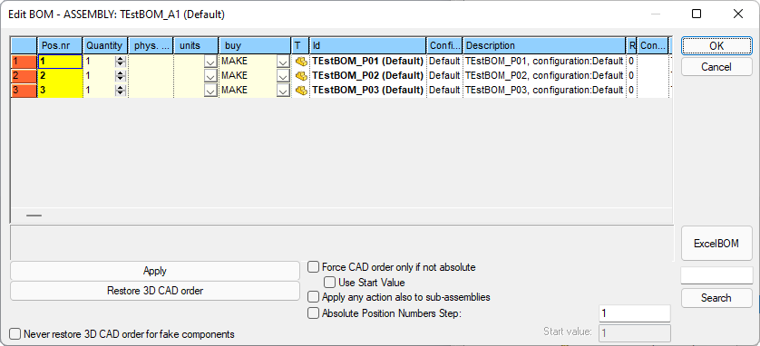
The dialog for setting the BOM is available from RMB→Bom→Edit BOM ...
It allows, in a centralized view, to set features and values for the BOM, in particular:
•BOM position
•Quantity
•Physical Quantity
•Unit of measure
•MAKE/BUY field value
RMB funcionalities
Some commands are available on the right mouse button menu:
|
|
|---|---|
|
|
|
|
|
|
|
|
|
|
|
|
|
|
|
|
|
Drag'n'Drop functionality to reorder BOM
One of the main capability of this dialog is the reordering of the BOM.
You can easily do it by drag and drop the row to the new position:
first select the record to move by clicking the row header (the row is black highlighted),
then click again the row header and drag the record to the new position (a red line shows the draggin target position),
finally drop the record on the new position.
MAKE_BUY field
If existing, the LST\PARENT_CHILD_MAKE_BUY.LST (localized for each language) is loaded for the MAKE/BUY values choice list; if file is not existing, values are taken from LST\MAKE_BUY.LST
Units field
If existing, the LST\PARENT_CHILD_UM.LST (localized for each language) is loaded for the units values choice list; if file is not existing, no value is shown.
BOM positions (the PARENT_CHILD_BOM_POS field)
PARENT_CHILD_BOM_POS is a text field of the PARENT_CHILD table, used by MechworksPDM as Absolute Position Number for the BOM.
The name of the field is language dependent:
Language |
field name |
type |
|---|---|---|
English database |
PARENT_CHILD_BOM_POS |
VARCHAR(10) |
German database |
ELTERN_KIND_BOM_POS |
VARCHAR(10) |
Italian database |
PARENT_CHILD_BOM_POS |
VARCHAR(10) |
French database |
PARENT_FILS_BOM_POS |
VARCHAR(10) |
Spanish database |
PARENT_CHILD_BOM_POS |
VARCHAR(10) |
The environment for the Parent-Child Physical Quantities
must be defined before defining the PARENT_CHILD_BOM_POS environment.
If the field is defined in the PARENT_CHILD table of the database, MechworksPDM applies the following behaviors:
•RMB→BOM / ExcelBOM functionality: the PARENT_CHILD_BOM_POS field is used instead of the dynamic PARENT_CHILD_INDEX, so producing always a BOM with the same components position numbers, independently of the physical order in the assembly itself; since the PARENT_CHILD_BOM_POS is a text field, position numbers like A01, A02, C01, etc. are allowed for the BOMs
•Buy list functionality: the PARENT_CHILD_BOM_POS values are inserted into the Excel file created by the function; items without a null PARENT_CHILD_BOM_POS are filled with the dynamic BOM pos ( read from the PARENT_CHILD_INDEX field ); items are then ordered by the PARENT_CHILD_BOM_POS field
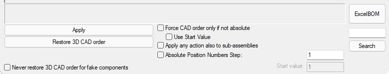
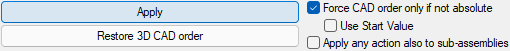
Values of the PARENT_CHILD_BOM_POS field are settable from the buttons and checkboxes in the bottom part of the Edit BOM dialog.
Please note these values are consistent through different sessions
Example
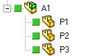
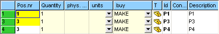
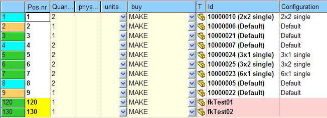
Suppose to have the assembly:
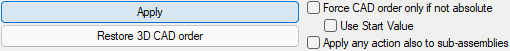
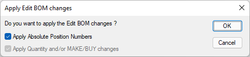
Suppose now to apply the current CAD native order by clicking the button:
you then will be asked (as for every operation) for a confirmation:
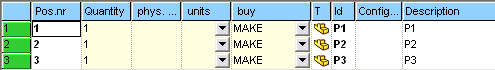
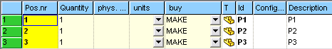
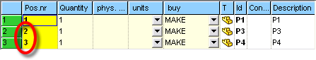
Now the Pos. nr. column becomes yellow
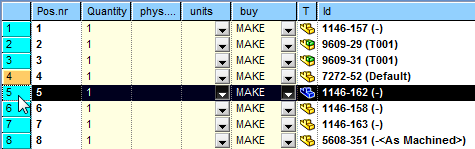
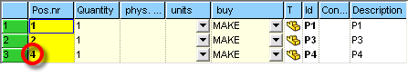
Suppose now to remove the component P2 and to add the component P4:
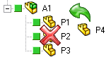
You obtain the following situation:
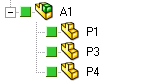
The Pos.Nr.3 is 3 – absolute for component P3, and 3 – cad order for component P4.
Of course, this situation would lead to inconsistent BOMs.
In order to fix this situation, the Force the current CAD native order can be applied in two ways (in red are the items that has changed):
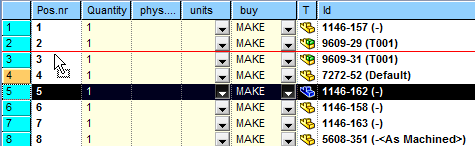
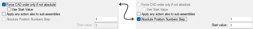
1.with the option ![]() Force CAD order only if not absolute not checked, clicking the button would change the position numbers as follows:
Force CAD order only if not absolute not checked, clicking the button would change the position numbers as follows:
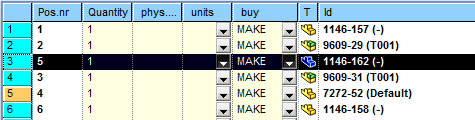
2.with the option ![]() Force CAD order only if not absolute be checked (please note the Absolute Position Number Step check becomes unavailable), clicking the button would change the position numbers as follows:
Force CAD order only if not absolute be checked (please note the Absolute Position Number Step check becomes unavailable), clicking the button would change the position numbers as follows:
Absolute Position Numbers Step
This value specifies, for components with NO absoulte position specified, the step the CAD value will be multiplied by to obtain an absolute position number.
In case the checkbox is unchecked (the AbsPos will be created only for missing one components), the generated value is multiplicated as well by the step.
Please note this checkbox is disabled if Force CAD order only if not absolute is checked.
Example
Suppose to have:
P1 AbsPos=1
P3 AbsPos=3
P4 ------------- (unassigned)
•![]()
P1 AbsPos=1
P3 AbsPos=3
P4 AbsPos=4
the AbsPos is calculated only for missing one (P4) and the value it's multiplicated by step 1
•![]()
P1 AbsPos=1
P3 AbsPos=3
P4 AbsPos=40
the AbsPos is calculated only for missing one (P4) and the value it's multiplicated by step 10
•![]()
P1 AbsPos=1
P3 AbsPos=2
P4 AbsPos=3
the AbsPos is calculated for every component and the value it's multiplicated by step 1
•![]()
P1 AbsPos=3
P3 AbsPos=6
P4 AbsPos=9
the AbsPos is calculated for every component and the value it's multiplicated by step 3
Sorting logic
To avoid any change of the native CAD order, order conditions has been summarized in 2 ways:
1.the native CAD order, with no Absolute BOM Position Numbers
2.the assigned Absolute BOM Position Numbers order
Due to this logic it is possible, when the native CAD order is still applied, to sort the BOM items by double-clicking on the ID/CONFIG/DESCRIPTION/... column’s headers and to apply the new order only as Absolute BOM Position Numbers.
Cleaning-up the Absolute BOM Position Numbers will RESTORE the native CAD order.
Never restore 3D CAD order for the fake components
If enabled, this option excludes any fake components BOM position that has been already assigned from the re-ordering.
Example
Let's see the different behavior of the button depending on the check setting.
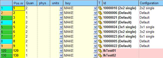
Please note the positions 120 and 130 are already assigned for fake components fkTest01 and fkTest02
•with the option disabled ![]() Never restore 3D CAD order for the fake components the result is
Never restore 3D CAD order for the fake components the result is
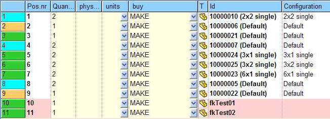
•with the option enabled ![]() Never restore 3D CAD order for the fake components the result is
Never restore 3D CAD order for the fake components the result is
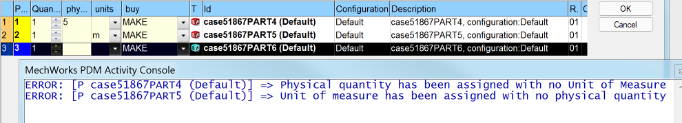
Validation on Apply
When pressing the button, a validation check on the Physical Quantity and Unit of Measure values is executed before applying any change to those fields.
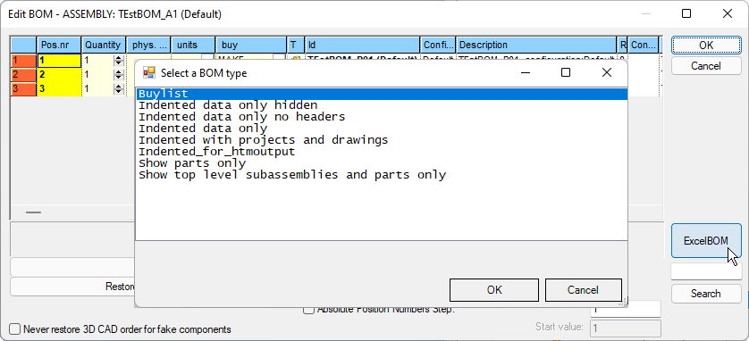
ExcelBOM
In the bottom right corner of the dialog there's an button that creates the ExcelBOM:
BOM items marked as NO_BOM do not increment the Absolute Position Number (PARENT_CHILD_BOM_POS) value, so to avoid gaps in the numeration when outputted through the ExcelBOM; this behavior matches the default SolidWorks BOM behavior.
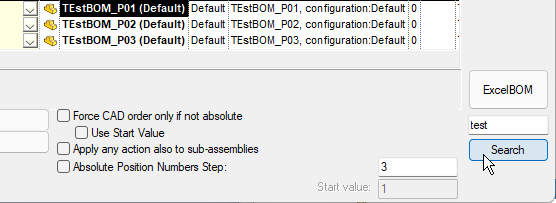
Search capability
In the bottom right corner of the dialog there's a button that allows to highlight components in the grid:
PARENT_CHILD_INDEX field
This field is used to determinate the belonging order of an item in a tree structure.
PROJECT as parent |
|
|---|---|
0 |
CAD Document |
0 |
Generic Document |
-10 ... -n |
Fake Document (i.e. Bom item) |
NOT PROJECT as parent |
|
0..n |
CAD Document |
-1 |
Generic Document |
-10 ... -n |
Fake Document (i.e. Bom item) |
-2..-9 |
INVALID values |
NULL |
|
Please note that generic documents inserted as attachments are not shown in tree structures.
PARENT_CHILD_RELATION_TYPE
![]() Users only
Users only
This field (that's language independent) is used to specify the parent↔child relation type between two related records.
Recognized relation type are:
Stock |
|---|
MirrorStock |
LPattern |
MirrorSolid |
CirPattern |
MirrorPattern |
Envelope |
When multiple relations (for example patterns of stocks) are detected, the relation type name is built as follows:
<first relation>@<second relation>@<third relation>
where the @<second relation> and @<third relation> can be empty.
Some examples are the followings:
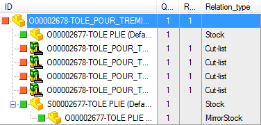
By queryng the database (PARENT_CHILD table) you can verify that every single relation between parent and child are marked in a different way:
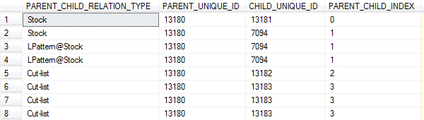
In the above case, the component with index = 1, appears both as a Stock, and also as a LPattern@Stock with two more instances
The DBWorks Browser is unable to display the instances, but this information can be used by programs that need to create customized Bill Of Materials.
PARENT_CHILD_COMPONENT_REFERENCE and PARENT_CHILD_INSTANCE_ID
![]() Users only
Users only
DBWorks will store in such fields (whom name is language independent) the SolidWorks Component Reference and Instance Id info attached to any instance of an assembly component:
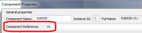
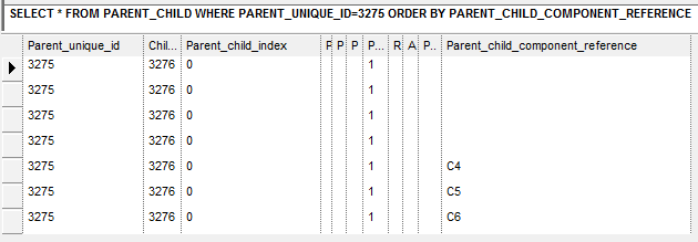
Please note there's no support for such info in the standard DBWorks BOM output - Customer's workflows that need such info must write their own BOM procedures
Field customization
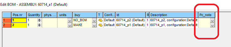
It is possible to define a section in the SCHEMA\Tables2.DFL file for declaring the fields to be displayed in the EditBOM dialog: the section header is EDIT_BOM for all the languages.
Each field can contain the PARENT_CHILD. Prefix (localized for each language) for displaying a PARENT_CHILD field
In case the EDIT_BOM section is missing in Tables2.DFL file, the COMPOSED_OF section will be used by default.
The first 4 columns (T, ID, CONFIGURATION, DESCRIPTION) are fixed so every customization will take effect only starting from the 5th column.
More, the HIDDEN property is not active for fields belonging to EDIT_BOM section of the tables2.dfl file.
Example
...
EDIT_BOM
T
ID
CONFIGURATION
DESCRIPTION
CNOTE
DESCRIPTION2
PARENT_CHILD.PARENT_CHILD_MY_FIELD
PARENT_CHILD.PARENT_CHILD_MYFIELD1
...
Direct field editing
You can specify the editabilty of a field through the keyword EDITABLE in the tables2.dfl definition file.
Example
...
EDIT_BOM
T
ID
CONFIGURATION
DESCRIPTION EDITABLE
...
The Parent_Child 'EDITABLE' custom fields will be shown with standard light yellow background and the changes will be effective in case of "Apply Quantity and/or MAKE/BUY changes" mode. Because of several record changes, from modification point of view, it is possible to change value via edit_text or via dropdown_list (in case of related .lst with a list of values).
Generic documents in the BOM
Generic documents are not included in the BOM, no matter what the MAKE_BUY field contains.
To include them you can:
•Create a New BOM Item and then associate its record to the generic file through the script Assign file to a record with non-existing file available from the shortcutbar.
•Enable the option General → More... → ![]() Add documents as BOM items.
Add documents as BOM items.