Link Mode Options
 Manage related drawings
The Link Mode enables DBWorks to manage and synchronize the revisions of parts/assemblies and the related drawings.
 Link only drawings with code beginning with the part code
If checked, DBWorks links only the drawings for which the ID begins with the ID of the part that has started the action. By default this option is left unchecked.
Please consider the following examples to clarify the way this option works:
Example 1
Consider the following case, with a drawing ( A1_01.SLDDRW ) with a code beginning with the code of one of the child document ( A1.SLDASM ):
•Assembly A1.SLDASM
oP1.SLDPRT
oP2.SLDPRT
•Drawing A1_01.SLDDRW
oA1.SLDASM ( Sheet1 )
oP2.SLDPRT ( Sheet2 )
oP1.SLDPRT ( Sheet3 )
Let's assume all documents are in revision 1.
•[ ] Link only drawings with code beginning with the part code unchecked (Default):
Increment the revision of P1.SLDPRT |
→ |
Revision of A1_01.SLDDRW automatically incremented |
|---|---|---|
Increment the revision of A1.SLDASM |
→ |
Revision of A1_01.SLDDRW automatically incremented |
Increment the revision of A1_01.SLDDRW |
→ |
Revision of A1.SLDASM automatically incremented |
•[X] Link only drawings with code beginning with the part code checked:
Increment the revision of P1.SLDPRT |
→ |
Revision of A1_01.SLDDRW NOT incremented |
|---|---|---|
Increment the revision of A1.SLDASM |
→ |
Revision of A1_01.SLDDRW automatically incremented |
Increment the revision of A1_01.SLDDRW |
→ |
Revision of A1.SLDASM automatically incremented |
Example 2
Consider now a case, with a drawing ( D1.SLDDRW ) with a code not beginning with the code of anyone of the children documents:
•Drawing D1.SLDDRW
oP1.SLDPRT ( Sheet1 )
oP2.SLDPRT ( Sheet2 )
•[ ] Link only drawings with code beginning with the part code unchecked (Default):
Increment the revision of P1.SLDPRT |
→ |
Revision of D1.SLDDRW automatically incremented |
|---|---|---|
Increment the revision of P2.SLDPRT |
→ |
Revision of D1.SLDDRW automatically incremented |
Increment the revision of D1.SLDDRW |
→ |
Revision of P1.SLDPRT automatically incremented ( it is the first ) |
•[X] Link only drawings with code beginning with the part code checked:
Increment the revision of P1.SLDPRT |
→ |
Revision of D1.SLDDRW NOT incremented |
|---|---|---|
Increment the revision of P2.SLDPRT |
→ |
Revision of D1.SLDDRW NOT incremented |
Increment the revision of D1.SLDDRW |
→ |
No revision incremented for children documents |
Always consider selected document's part code
When a drawing has a different code than the model, the revision actions are considered in a priority way. This option avoids to apply this priority.
Example
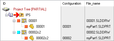
Suppose to have checkedin structure made of a part MyPart1.sldprt with configurations 00001 and 00002 (with respectively 00001 and 00002c2 as IDs) and with one drawing for each configuration (with the same IDs of the parts: 00001 and 00002c2):
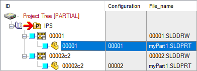
then perform a RMB on the part and Check In/Out → Check-Out
•![]() option disabled
option disabled
 → the revision action has not overriden the link mode option
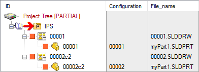
•![]() option enabled
option enabled
 → the revision action has overriden the link mode option
A typical usage of this option is when the user (since of his particular ways of managing drawings of configurations) can assure that the 00002c2 drawing is totally independent from the 00001 part's configuration.
Get Main Document from First Sheet's Properties
This option permits to align the behavior of the Link Mode for the relation Drawing - Model to that of SW.
Normally the main document of the Drawing↔Part Link Mode is the first inserted in the drawing. This corresponds to the first external reference listed in File->Find References… with the drawing opened in SW. Now, since with SW you can assign, in the Sheet Properties, the View of the drawing containing the model that will be used for getting the custom properties for populating the drawing’s title block:
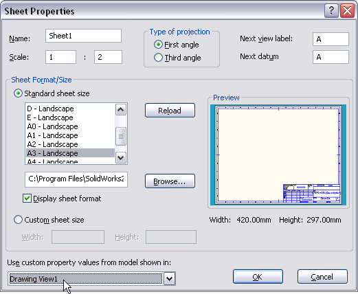
checking the above DBWorks option causes the Drawing↔Part Link Mode to consider the same model as main document, and to align consequently the revisions and states with that model.
This new features is not backward applicable: the drawings need to be saved at least one time with the option checked, because the information on who will be the main document of the Drawing↔Part Link Mode is read from the PARENT_CHILD table, looking to the child documents of the drawing itself, and getting the one with the PARENT_CHILD_INDEX equal to 0.
Link referenced Drawings/Parts even if checked-out by others
When checked it makes possible to checkin/approve drawings/parts created by other designers, but referencing the same documents.
Example
A typical example of use is when multiple designers works for making multiple drawings of the same part.
Suppose User1 creates a Part1 and its Drawing1, and keeps it in checked-out state.
Now User2 opens the Drawing1 and creates a new Drawing2 of Part1.
Without this option, Drawing2 and Part1 (and so also Drawing1) will always be not linked, because the check-out-by users are different.
By activating this option, it will be possible for User1 to CHECKIN/APPROVE the Part1 and Drawing1, and have Drawing2 be checked-in/approved as well.
At the same time, User2 would be able to CHECKIN/APPROVE Drawing2, and have Part1 and Drawing1 be checked-in/approved as well.
Always 'Save As' all the linked Drawings
At every 'Save As' of a Part/Assembly, MechworksPDM will look if any linked Drawing is existing, and if so, it will Save As the drawing as well, replacing the references in the new drawing with the new document just saved.
Use DataEntr.LST
Reopen after a 'Save As'
This option allows to reopen automatically the new saved drawing documents if the old related ones are opened when the 'SaveAs' command is executed.
After command execution, the old opened drawing documents are still available to have a more compatible environment.
For SolidEdge, due to some API limitations (see IR 1963247), to allow right access on new drawings (after custom property management) the documents must be closed and then re-opened.
Align Drawings↔Part Fields
this option activates the alignment of the fields every time one of the document or drawing records are updated in any way. It replaces the old (and now obsolete) [X] Align Drawing↔Part fields on Checkin.
DOCUMENT and REVISIONS fields are supported. Mind that the part/assembly->drawing may be a one to many relationship.
New drawings have the Input Form already populated with the Part/Assembly record fields values declared
Please note when you declare a field to be aligned, such field must be present in both DRAWING and PART database views.
Example
If you declare DOCUMENT.TREATMENT, if the field TREATMENT is not included also in DRAWING view (despite of the fact the treatment is a models specific field) an error message will be shown: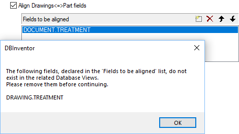
Manage derived parts
If checked, MechworksPDM manages all the relationships between the derived parts, at checkin, checkout and approval time. This means that all the parts and assemblies that need to be implicitely modified because of a modification in a linked part, are automatically checked-in, checked-out or approved.
Because of this behavior, if you leave the option unchecked, you can avoid the automatic checkout of all the derived parts when a base part is checked-out for modificaton.
If the modification will affect only feature not related to any derived part, there will be no need to check-out the derived parts as well.
If instead the modification will affect features related in some way to derived parts, a message will be displayed alerting you that you need to check-out other components before proceeding to the modification of the feature.
More, if the component is in checked-in state, a button [CHECKOUT] is available so to checkout on the fly the component.
Note: since of a limitation in the reload api of SW, not callable after having started the editing process, the CHECKOUT feature is NOT AVAILABLE when running in Local Checkout Mode.
As an alternative, you can check the option Environment->[X] Always notify editing of read-only components, which displays a notification avoiding to automatically checkout all the derived parts when a base part is checked-out for modificaton.
Avoid linking of documents like:
Enabling this option, you can assign a list of patterns to define groups of files on which the link mode is not active.
Example
Suppose you have the following tree structure:
A1
-BasePart1
-P1
--BasePart1
-P2
--BasePart1
-P3
--BasePart2
If you modify the state of Base1part, automatically the state of Asm1, P1 and P2 is also modified.
Suppose now you avoid linking of documents like:
[base1*]
If you modify the state of Base1part, no actions will be taken on Asm1, P1 and P2; instead if you modify the state of Base2part, the state of P3 and Asm1 are modified automatically.
Align Part↔Part fields
Allows to keep aligned the assigned fields between records of derived parts with their base part or viceversa
Manage Cut lists
Align Part↔Cut list fields
This option is for Solidworks users only
This option can be enabled only if the following option is already enabled
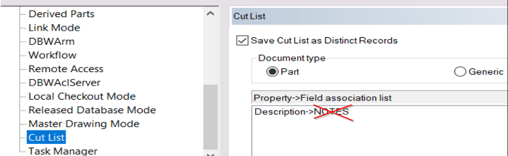
Environment → Cutlist → ![]() Save Cut List as Distinct Records
Save Cut List as Distinct Records
Allows to keep aligned the assigned fields between records of cut list with their base part or viceversa.
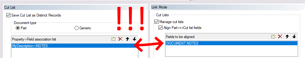
to avoid conflicts, make sure that a field (e.g. DOCUMENT.NOTES) is not present in both field lists at the same time.
Align only in direction Part→Cut list
self explaining
Keep brothers Cut list aligned
This option propagates the modification of a single cutlist value to all the other cutlist records.
Manage Child Generic Documents
This option makes the Link Mode manage also the attachments of Generic Documents ( descendants to the main documents ).
Manage Parent Generic Documents
When checked, the Link Mode will also consider any Generic Documents that is a Parent of Parts/Assemblies.
A typical usage of this option is for keeping aligned the revisions of parts that have been created for migrating legacy file formats into 3D file formats
![]()
Enable full Link Mode on Documents with the same ID
When enabled, the child Generic Documents are checked against their ID for calculating the Linked Documents relations, and any other document with the same ID will be considered a Linked Document, so having its state and revision be managed by the Link Mode functionality.
More, when this sub-option is enabled, when adding a new Generic Document by using the Add document… or Drop functionality, the state and revision of the added Generic Document will be aligned to the state and revision of the group of documents with the same ID, in a way similar to the Add configuration functionality.
Automatically create PARENT-CHILD relations
With such option activated, the behavior of the application affects the initial creation of the DOCUMENT record by automatically creating also a PARENT-CHILD link with the following rules:
•If a Generic file already exists in the database and the user attempts to insert a Model (SolidWorks/Inventor/SolidEdge) with the same exact ID as the Generic file, then:
oif the Generic file is a 2D Drawing file (DWG/DXF/ME) then automatically create the Parent-Child relationship where the 2D Drawing file file is the Parent.
oif the Generic file is a Generic document file (like an MS-Office file) then automatically create the Parent-Child relationship where the Generic Document file is the Child.
•If the Model already exists in the database (SolidWorks/Inventor/SolidEdge) and the user attempts to insert a Generic file into the database with the same exact ID as the Model, then automatically create the Parent-Child relationship where:
oif the Generic file is a Generic document file (like an MS-Office file) then automatically create the Parent-Child relationship where the Generic Document file is the Child.
oif the Generic file is a 2D Drawing file (DWG/DXF/ME) and the Model already has a Parent 3D-CAD DRAWING file, then the 2D Drawing file is automatically set as a Child of the Mode
oif the Generic file is a 2D Drawing file (DWG/DXF/ME) and the Model does NOT have a Parent 3D-CAD DRAWING file, then the 2D Drawing file is automatically set as the Parent of the Model.
SQL Filter Condition.
Filter with the SQL syntax for discarding/accepting relations with descendent generic documents
Example
FILE_NAME LIKE '%.DOC' OR FILE_NAME LIKE '%.XLS' AND NOT ID LIKE '123*'
In the SQL definition are supported also macro such as $(ID), $LASTREV()
The following condition links only the child generic documents for which the ID is the same of the parent model
ID='$(ID)'
Include linked documents when deleting
This option will automatically include any linked document in the Selection Dialog of the Delete functionality.
Include preview of Linked Documents in Recursive Revision Operation Dialog
When enabled, the Document Selector Dialog shows, as additional info only, also the list of Documents that are Linked (following the rules of the Link Mode) to the Documents that will be processed for the Recursive Revision Operation. Such list is always displayed after any selected Document, and separated by a gray bar: 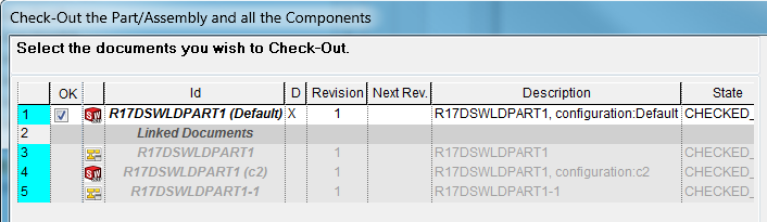
Include linked documents when assigning/changing the Project
This option will automatically include any linked document when a document is moved under a different project, or included into a new one; in particular:
a.RMB→Projects→Add To/Remove From Project: any linked drawing, configured brother or derived part is added/removed as well
b.Drag&Drop on a Project: any linked drawing, configured brother or derived part is added to the target project, detaching it from the old project if the CTRL key is kept pressed while dragging
c.Projects↔Documents Management: any linked drawing, configured brother or derived part is managed as well
d.Save of a document when the Options→Projects→[ ] Avoid automatic parent document project assignment is unchecked: any linked drawing of the child components is inserted in the current project as well
Also for configurations
It controls whether the Link Mode must be applied or not applied when adding/removing a configured record from a Project
Use OnFilterUids.LST to filter the uid list
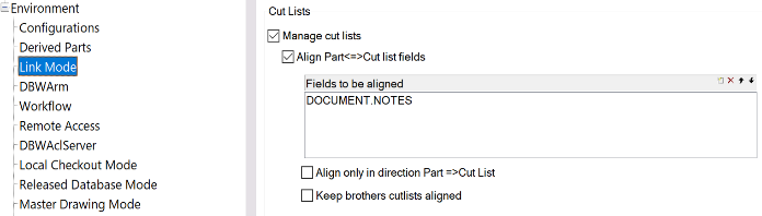
Align Part ↔ Cut Lists fields
This option of Environment->Link Mode->[X] Manage cut lists, together with the Fields to be aligned list, permits to keep aligned the assigned fields between records of Cut Lists with their base Part or viceversa.
Note well: be aware that option Environment->Cut Lists->[X] Property->Field association list can conflict with the behavior of this option, to avoid conflicts be sure that the field to align(e.g. DOCUMENT.NOTES) is not present is not present also in the Property->Field association list.
Align only in direction Part =>Cut List
Enable this option to allow alignment only from parent Part fields to child Cut List fields, the alignment child Cut-list -> parent Part won't be executed.
Keep brothers cutlists aligned
Enable this option to allow alignment occurs not only from the cut list fields to the parent Part fields, but also from the cut list fields to the other child cut lists fields that belong to the same parent Part.