Tree options
 Explorer Project Tree Mode
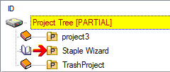
 Standard Project Tree mode
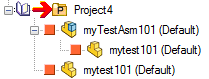
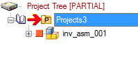
By selecting the Explorer Project Tree mode, the upper tree will contain projects only, clicking one project in the project tree will populate the lower tree with the content of the upper tree selected project; See specific topic.
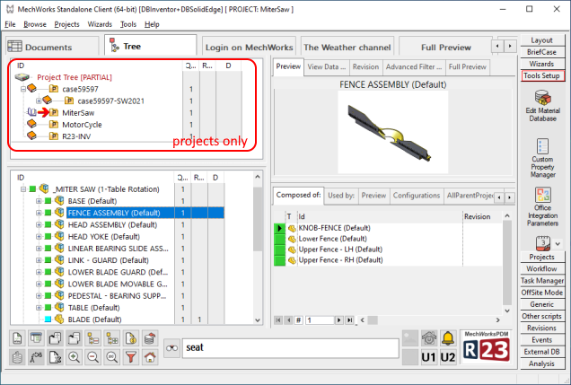
This mode will notably enhance the performance of the control.
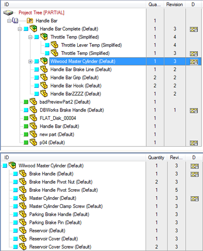
The Standard Project Tree mode is the R20 standard mode, with documents and projects in the same strucutre.
 Populate Child/Parent Tree in the Sub-Tree
If checked, the output of the RMB→Child Tree/Parent Tree action is shown in an additional Tree Control (named Sub-Tree) rather than in the common Project Tree.
Example
Show the value in a column beside the Tree:
 Existing drawings
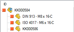
If checked, a drawing icon is shown in the right-most column to indicate the presence of at least one drawing for the part/assembly enlisted in the Tree.
If more than one drawing is related to the current record, a special icon with 2 drawings is shown instead of the default one.
![]()
If you rightclick (RMB) on the icon in the Drawing column, you'll obtain the same popup menu you'd have by clicking on a drawing record; this is very useful if you don't show drawings as nodes in trees.
![]() Solidworks users only
Solidworks users only
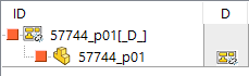
If the drawing is detached, the common drawing icon will be replaced with the specific detached icon and an additional [_D_] string is shown in the tree:
Physical quantities
If checked, and if the physical quantities environment is correctly set, MechworksPDM displays the physical quantity of the items in the Tree Page. Read the topic Change quantity for details on the activation, that may require modifications in the database structure. To see an example of resulting display, please read the topic The Tree window.
BOM quantities
If checked, a column with the Quantity is shown in the Trees
COMPANY_ID
If this option is checked and the Remote Access is active, a column with the COMPANY_ID values is shown in the Tree Page
REVISION
If checked, a column with the revision values is shown in the Tree Page
MAKE_BUY
If checked, a column with MAKE_BUY values is shown in the Tree Page.
Please note this option shows the DOCUMENT.MAKE_BUY field. To visualize the PARENT_CHILD.MAKE_BUY field you've to use the Extra PARENT_CHILD or Linked Database Tables Columns to show in the Trees option.
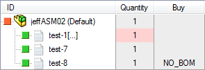
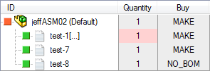
Filter MAKE value
If enabled the value MAKE (default) won't be shown in the tree (to keep the visualization lighter).
|
|
|---|---|
option disabled |
option enabled |
Extra DOCUMENT table fields:
In this list, choosing from a dialog, it is possible to specify other columns (fields of the DOCUMENT table) to show in the tree structure interface of the Tree Page.
Please note this option drives also the fields to be shown (adding them to defaults ones, not hideable) in
•briefcase
•reload of skipped components
•ownership change of Remote Access
•document multiple submission to workflow
•ShowDocumentSelectorDialog shell command
Extra PARENT_CHILD or Linked Database Tables fields:
In this list, choosing from a dialog, it is possible to specify other columns (fields of the PARENT_CHILD table) to show in the tree structure interface of the Tree Page.
Use of an existing DOCUMENT field with the same name
The Tree is able to display the DOCUMENT table value of a field if the PARENT_CHILD field with the same name has a null value.
Example
•Parent_Child field: PARENT_CHILD_MYFIELD
•PART view field: MYFIELD
If PARENT_CHILD_MYFIELD is declared in the option like this:
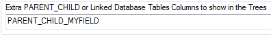
then, if the PARENT_CHILD_MYFIELD value is null, the DOCUMENT::MYFIELD will be displayed for the Tree item;
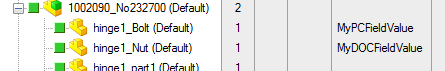
in the following picture, the "hinge1_Bolt (Default)" part has a PARENT_CHILD_MYFIELD value equal to "MyPCFieldValue", while the "hinge1_Nut (Default)" part has a PARENT_CHILD_MYFIELD value that is null, but the PART::MYFIELD value is equal to "MyDOCFieldValue"
Show drawings as nodes in the Trees
With this option checked, drawings are explicitly displayed in the Project Tree
Please note that the appareance of the Project Tree could substantially change due to the parent-child relationship between a drawing and its component.
Show only unreferenced drawings
Some drawings can exist with no link to any model (e.g. 2D drawings in Solid Edge);
by enabling this option you will see in the Tree the unreferenced drawing only, otherwise to see them you would have to see also every drawing, included the ones with a 3D model link to it:
On the left the option is disabled (see all drawings in the Trees); on the right the option is enabled (hide drawings with a linked model and show the unreferenced ones in the Trees).
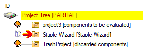
Show project descriptions in the Project Tree
If checked, MechworksPDM displays the project descriptions in the Project Tree, This option should be checked when the ID is a numeric code and should be left unchecked when the value in the field Description is very long or when the ID itself is self-describing.
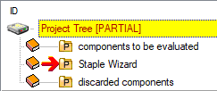
Show ONLY description
If checked, displays only the Projects Description in the Project Tree, instead of concatenating it to the Project ID.
Example
|
|
|
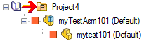
Show only top level objects in the Trees
If checked, MechworksPDM displays only the top level objects (main assemblies) in the expanded branches of the Project Tree.
|
|
|---|---|
option enabled |
option disabled |
Note: this feature can have a significant negative effect on the tree rebuilding speed, so you should avoid to check it if managing projects with thousands of components.
Expand the current project in the Project Tree and collapse all the others
If checked, MechworksPDM always expands the current project everytime it is set. By default, active.
Max number of expanded sub-projects levels in Project Tree
It is the max number of expanded sub-project level in the Project Tree.
The current project is visible indipendently from the value of this option.
In order to improve tree rebuild performances it is recommended to keep this value as lower as possible.
The value 0 (zero) disables the forward check for any existing sub-project while populating the Project Tree. This leads to a huge performance enhancement when populating very large project trees (10.000 and more) - the negative effect is that the ![]() plus sign is ALWAYS displayed even if a project does not have any subproject under it.
plus sign is ALWAYS displayed even if a project does not have any subproject under it.
Example
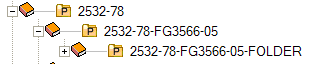
The subproject 2532-78-FG3566-05-FOLDER has no subprojects but the plus icon is shown as well.
Mark parent-child relation according to external reference
This option, for Solidworks users only and formerly defined under options→Environment→Derived Parts has been enhanced and moved to this UI section of options
It now applies not only to derived parts but also to assemblies, ensuring a more consistent handling of external reference information across different saving operations.
This option improves the tracking of external references between parts and parent models.
By saving a derived part/assembly, the system will register child models also in case of Locked, Broken references.
The data is recorded in the table PARENT-CHILD.PARENT_CHILD_REFERENCE_STATUS (see here).
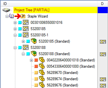
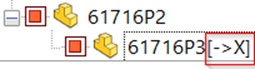
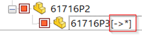
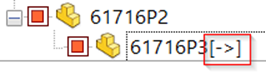
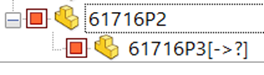
This management ensures that the references are also reflected in the PARENT-CHILD table; a symbolic notation is appended next to each tree item child ID to indicate the specific reference status.
Here are the external reference possible values and relative symbols:
state |
displayed as |
PARENT_CHILD_REFERENCE_STATUS |
Tree UI |
|---|---|---|---|
Broken reference |
[->X] |
0 |
|
Locked |
[->*] |
1 |
|
In Context |
[->] |
3 |
|
Out of Context |
[->?] |
4 |
|
This approach makes it easier to identify the state of the external parent model toward its dependencies directly from the relationship data, including references that were previously ignored if marked as Broken or Locked.
Remarks:
In case the parent model (P2) contains multiple references to the same source model (P1), each with a different external reference status, the PARENT-CHILD table records the status with the highest precedence, determined by the following severity:
•The broken reference state takes precedence over all other states.
•The locked reference state takes precedence over all other states except the 'broken' state.
•The In Context reference state takes precedence only over the 'Out of Context' reference state.
•The Out of Context reference state does not take precedence over any other states.
Enable drag-and-drop in the Trees
If checked, MechworksPDM enables drag & drop operations in the Project Tree and in the Tree Page. It is also possible to drag & drop a file in the SW desktop directly from any Tree Control item, starting to drag from the item label; multiple selections are allowed.
By default, this option is unchecked.
Enable drag-and-drop on Assemblies
This option allows the drag & drop on assemblies.
Only for fake components
This option allows the drag & drop of components into existing assemblies only if the components have been created with the Create New Bom Item functionality (fake components).
Highlight 'dirty' revision documents in the Tree (and Grids)
If checked, and if the 'dirty' revision flag environment is correctly set, MechworksPDM highlights in the Trees the released documents that have the DIRTY_REVISION_FLAG value not null.
See specific help topic.
Even for documents in CHECKED-IN/CHECKED-OUT state
if this option is enabled, the dirty status is highlighted also for states of checkin and checkout (being_modified).
Highlight 'fake' components and quantities in the Tree
If checked, MechworksPDM highlights in the Trees the components that have a 'fake' quantity assigned using the Change Quantity. functionality.
Highlight records not updated in the DB
If checked, MechworksPDM highlights in the Trees the components that have been saved through the CAD application but (due to the CTRL+Save action and options) haven't been updated in the db yet.
Working with the option
Environment → ![]() Enable CTRL key for executing native CAD 'Save'
Enable CTRL key for executing native CAD 'Save'
or
Save → ![]() Always update database structure on checked-out document save
Always update database structure on checked-out document save
it is possible to keep track of not updated record at database level.
Based on the field named CTRL_SAVE_FLAG (same name for all the supported languages) available in the DOCUMENT table, the field keeps track of record with no updated information based on the last save operation performed: the value 1 indicates that only a CAD save operation was performed without updating the PDM database structure.
The value of this field is reset to NULL each time the database structure is updated for the specific record.
This option allow to highlight at browser level the record with no updated DB information: the involved records are marked with a specific icon both in the Browser at tree/grid level:
At Event log, the corresponding events are dumped as ASSEMBLY_SAVE_NO_DB_UPD, PART_SAVE_NO_DB_UPD and DRAWING_SAVE_NO_DB_UPD.
Show descriptions in the Trees
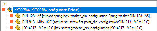
If checked, the Project Tree displays both the IDs and the Descriptions of the Tree items. This option should be checked if the IDs are numeric or codes and an explicit description can help the designer to identify items in the Project Tree.
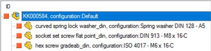
Show ONLY description
If checked, the Project Tree displays only the Descriptions of the enlisted items Projects.
Example
|
|
|
Hide Inventor Presentations in the Trees
When checked the .IPN Presentation documents will not be displayed in the Tree
|
|
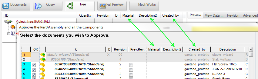
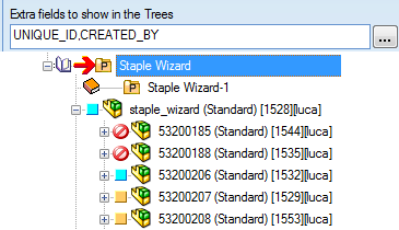
Extra fields to show in the Trees
MechworksPDM allows to add fields to the tree, indicating them in the text box separated by commas (example: COST,ITEM_CODE,SUPPLIER_ID); we suggest not to use many fields in order to continue to have a good performance on tree regeneration.
Here's a valid example and the generated result:
Avoid Child Tree for Documents with File Names like...
You can define file patterns to exclude files from being included in the child tree.
Avoid Parent Tree for Documents with IDs like...
You can define ID patterns to exclude records parent tree from being shown.
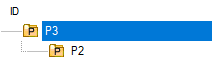
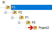
Example
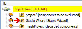
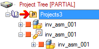
Suppose you have this structure and settings:
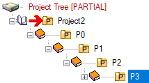

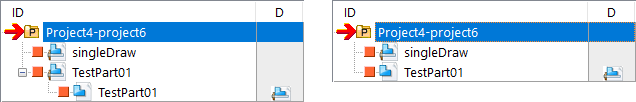
When performing a RMB→ParentTree on P3 you'll see different behaviors:
|
|
Visible Grids:
It is possible to selectively display specific Grids in the Tree Page.
This option can be filled with the identifiers of the Grids that must be visible in the Tree Page interface.
When the Option is empty, ALL the Grids will be available.
All the LST\OnCustomQueryTab_xxx.LST are available in the choise combo box.
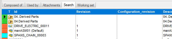
For example, with the following setting:
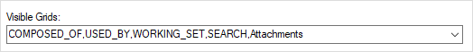
the Grids area of the Tree Page User Interface will appear as:
Notes: it is not possible to control the ORDER of the Grids, but only their visibility.